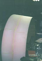
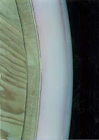
| My next big job was/is the Thrust duct. This proved to be the most intimidating part of the construction for me thus-far. Construction consists of making two 48" diameter disks, attaching the disks together via 3" blocks and then wrapping the disks with 1/8 plywood to serve as the duct wall. The plywood is then wrapped with two layers of 1" polyurethane foam. I used that urethane foam that comes in spray cans to glue the foam together and to the plywood. | ||||||
| The second layer of foam was glued to the first layer with a 3/8" overlap to form the duct lip. You'll see pictures of the formed lip a little later. This view is useful to see the disk attached to the plywood attached to the foam layers as well as a plywood joint (I used epoxy to join the sections of the duct wall together). | ||||||
| I mounted the 48" diameter duct assembly on a 1" shaft which I mounted to my bench via 2 pillow block bearings (which I bought to use in the finished hovercraft to drive the propeller shaft). I affixed a 12" swamp-cooler pulley to the shaft and drove the contraption with my old Maytag washing machine motor via a 58" belt and 1 1/2" sheave. | ||||||
| This is a closeup of the drive motor which I strapped to the bench with plumber's strap. This motor spins in either direction at 1750 RPM. The shaft spins at around 146 RPM, and the outside edge of the duct is moving at around 15 fps and has a massive amount of inertia. Why did I want to spin the duct at 146 RPM? Because then I can shape the foam like a lathe. I borrowed the idea from http://www.hoverclubofamerica.org/fmduct.html. | ||||||
| This view shows how the shaft goes through a 1" hole in the plywood disks... | ||||||
| ...to this side where it spins a small pulley which then spins the thrust duct. The arrows are pointing at the adjusting devices I used to adjust the duct's balance on the shaft. The balancing gadget consists of a 1.5" hole in this disk and 4 'clamps' that allow me to straighten the duct on the shaft by moving a piece of wood in or out and tightening a screw. Once I acheive the proper alignment, I insert another screw in each of the 4 clamps thus affixing it in a set position. Why did I need to adjust the alignment? Well, even I'm not perfect... *sigh* | ||||||
| Finally, I could start shaping the duct. Before I started sanding, I rough cut the basic shape I was trying to get with a hot-wire which saved me alot of sanding. When that was done, I spun the duct up and started sanding on it with 50 grit. The lines you see are the uneven spots I had marked while the duct was spinning. | ||||||
| This is what the duct looked like when I finished smoothing it out with 100 grit. The sanding block was a 2x4 about 18 inches long to make the angled backside of the duct as straight as possible. | ||||||
| I basically just free-handed the lip by just holding a piece of sand paper against the foam and shaping the lip with my fingers kinda like using a potter's wheel. I would occasionally shut down the spinning motor and check the shape with a template I cut out of 1/8" plywood (Hmmm... a little more off the top). | ||||||
| And this is how the duct shaped up when I was done. | ||||||
| When the sanding is finished, it's time to glass. This is a major hassle that's only slightly improved by having the duct mounted on a spindle. Nope, I didn't spin it up while glassing on account of it would toss all my hard work right back in my face... literally. This job took 2 layers of 1.45 oz./sq. yd. fiberglass cloth (Good stuff to work with compared to the 6 oz cloth) and about 5 coats of Epoxy resin. I recommend West resin available from St. Louis Hovercraft. Get the handy-dandy measuring pumps too. Makes the job of measuring resin to hardener easy and precise. | ||||||
| Duct is done. Time to make the duct support fins that keep the duct stable when mounted on the hull. The fins are constructed by cutting the shape out of 1/2" thick piece of foam, sanding the foam to a fin shape, and then epoxying a rounded piece of wood to the leading edge. | ||||||
| Finally you slap on two layers of 6 oz glass and sand them to perfection... well, use your imagination. I'll actually need 4 fins but decided to make just two at this time because I haven't decided how to attach the final two fins to the craft since the plans make it look like I'm supposed to cover one of the thrust bearings with a permanent plywood structure which I really don't feel comfortable doing for maintenance reasons. More on that later. | ||||||
| To mount the duct, the first thing that has to be done is to carve a flat spot on the duct where the duct is to be mounted on the hull. I accomplished this by mounting the bearings and shaft that I had used to spin the duct where the prop shaft and bearings will be mounted on the rear of the craft. Before doing this, I had to find the true center of the hovercraft regardless of where I placed my bearing mounts. Turns out that center was about 1/2" to starboard of where the bearing mount centerline is... *sigh*. After mounting the bearings and shaft, I fitted the duct with discs in place back onto the shaft. I could then sand off a portion of the duct, slide the duct forward until it contacted the hull, slide it back, sand some more, etc. This was actually a difficult task since the _inside_ of the duct was to be aligned with the prop shaft and the back of the duct is slanted one way, and the back of the craft is slanted down the other... *shiver*. This picture is taken straight on at the flat spot. You can see the shaft and rear bearing (and mount) to the right. The duct has been slid back for sanding. | ||||||
| This is what the duct looked like when it finally fit where it was to be placed. There was a slight bit of error but I think I'm happy with it in general. | ||||||
| After I mounted and epoxied the duct to the hull, I installed the two fins that I'd constructed earlier and kicked out the discs that had been used to form the duct. Holy cow! It's starting to LOOK like a hovercraft! | ||||||
| Here's a view of the duct from the front with my experimental cat-o-matic thrust system. After several hundred man-hours (and cat-hours) of training and experimenting, my crew of engineers and I just couldn't get Snowplow to spin his tail fast enough to provide the necessary thrust so the project was scrapped (scratched? heh). | ||||||
| The plans called for a couple of 10" diameter discs made out of 1/4" plywood to be glued to the rear bearing mount and a piece of wood at rib 5. The discs were to be covered with 1/8" plywood on top of which the top duct support fins were to be mounted. This troubled me because I felt that the dome would get in the way of maintaining the thrust bearings and engine. I decided to build a higher dome made out of 3/8" ply. I'm confident that this assembly will be just as strong and not much heavier than the original and it will provide good access to the engine, bearings, and shaft. I will post pictures of the finished dome and top duct support fins very soon. | ||||||
| Since I've added quite a bit more weight to the hovercraft, I felt it necessary to beef up the gear used to hang the craft from the ceiling. I bought some 3/8" steel cable, ferrels, and heavy-duty clamps and replaced the nylon rope previously used to connect the hovercraft to the lower pulley. This is a bad picture of the craft hoisted to the ceiling so my car can use the garage too. | ||||||


